


See also:
Send an inquiry:
We design innovative solutions to fully meet the individual needs of our customers.
If you haven't found the right product or you want to send an inquiry for an existing one, please contact us:
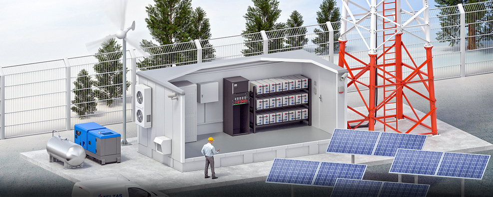
FC-01 System
The FC-01 fuel cell system is based on FCO 2.5 hydrogen fuel cells. The system consists of two parts:
- a gas tank with hydrogen cylinders
- hardware in which FCU 2.5 fuel cells are installed
The operation of the system is supervised by the Jupiter MCU driver. The system is enclosed in an outdoor cabinet. Its task is to fully protect the equipment installed in it against the negative impact of environmental factors and against the interference of unauthorized persons. An important task of the cabinet is to maintain specific thermal conditions inside it, adapted to the equipment installed in the cabinet.
CHARACTERISTICS
- power scalability from 2.5 to 10kW;
- easy to use;
- efficiency > 50%;
- fuel cells are smaller and lighter than conventional solutions such as lead-acid batteries or diesel generators;
- wider operating temperature range compared to batteries;
- low complexity and high reliability;
- solid construction: excellent protection against corrosion, dust, vandalism and break-ins;
- two separate chambers for the installation of: - 50l hydrogen cylinders, - FCU 2.5 fuel cells;
- fuel cell and controller modules are plug & play - it facilitates installation, start-up, operation and maintenance;
- the possibility of expanding the cabinet and increasing the key parameters of the power supply system;
- resistance to difficult climatic conditions;
- thermodynamic functions of the cabinet: - cabinet heating in periods of reduced temperature, - ventilation in periods of increased temperature;
- AC and DC distribution panel.
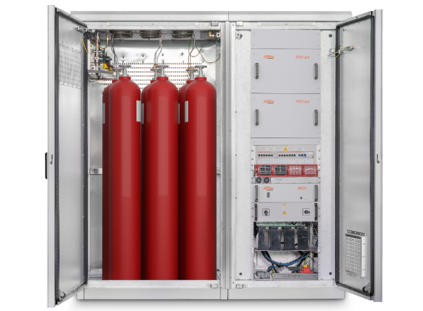
SYSTEM BUILDING
Working Fuel cell modules are designed to be connected directly to the 48 VDC rail. In standby mode, the fuel cell system draws less than 50W of power and requires connection to an existing DC power system. An external battery is required to boot the system. The cabinet consists of separate spaces for various purposes and thermal conditions adapted to the devices installed inside:
Fuel Cell Chamber
The chamber is thermally insulated and can be heated or ventilated in case of very low or very high temperatures. The air used for ventilation is supplied through a separate duct from the air supplied to the fuel cells used for the electricity generation process. The air inlet and outlet ducts are located on the rear wall of the fuel cell chamber. There are cable grommets in the chamber.
Hydrogen chamber
The hydrogen chamber is directly connected to the fuel cell chamber. The first one contains a management module with a pressure reducer, pressure sensors and valves. For easy access to all system components, tubing is located in the upper part of the housing.
DOCUMENTATION
Catalog Card- FC01
4/24/2024 8:00:43 PM